Inglish version.
Description of the device
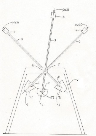
We would probably hardly expect precession of the flywheel(3) together with its drive(4) and drive plate(5) on which rests around the pin of precession(1) at the same justifikation as the flywheel(3) is rotating. In the case described on this enclosed picture(look at model p. and shema in fotoalbum),the driveplate slides with its curved end,stiffened by felt.on the smooth leveled base lamella(6) resting on four braces.It overrides the friction caused by compound of weight of the flywheel(3) together with its drive(4),which presses the plate of drive(5) to the lamella of frame(6). Concrete value of the factor of friction regarding to the pin of precession(1) is 1,6Ncm. Joint(9) enables the variation of the plate of drive(5) at the level of the pin of precession(1) and the pin of rotation(2). The angle of inclination of the plate of drive(5)regarding to the pin of precession(1) is moving between 45+-10 degrees.The lamella of the frame(6) is made from 2mm thick polished aluminum identical to the plate of drive(5).Flywheel(1) is manufactured from the steel with the diameter 58,6 mm,thickness 5mm and mass 114 g.Direct electric device is used to propel the flywheel working with Voltage 3-9V and pover 1,1-6,6A.Maximum revolution of the electric device is 11600RPM. The source of power is dry battery 12V 6,5Ah. Power from the battery goes to the pulse electronic regulator which in conjuction regulates revolution of the electric device. Power(10) from electronic regulator is directed into electric device through spring cooper connection and collective rings fastened on the precession shaft. Positions(8) on the picture there are two small plates from the sama material,one of them is fastened on the front and the other on the back on flywheel(3). Both small plates are at same distance from the rotation pin of the flywheel(2) Disk position(7) is fastened of the precession shaft.
Experimental results
As far to the precession alone and mainly its revolution, experiments provided on the described device show,that the revolution of precession increase first with the revolution of the flywheel(3) and mass of a small plates(8).During experiments two couples of small plates with different mass were used.One had mass 0,4g and second had mass 2g. Distance between both couples of small plates and rotation pin(2) flywheel(3) was the same and had value 26 mm. To mesaure rotation of the flywheel(3) digital opt-electric RPM gauge with measurement range 10 000 - 20 000 RPM was used.
Result of measurements
Mentioned values represent average values from the series of measurements.
rotation of the flywhel rotation of precesion
Small plates mass 0,4g 4260 RPM 4,6 RPM
6450 RPM 4,7 RPM
11600 RPM 6,0 RPM
Small plates mass 2g 3870 RPM 6,0 RPM
5680 RPM 15,0 RPM
7500 RPM 30,0 RPM
Discussion
Results of the measurement show that the mass of small plates has the main effect on the size of the revolutionb of precession. In the meantime while the revolution of precession with the application of small plates with mass 0,4g is rising with increase of flywheels revoluton very slowly, increase of the revolution of precession with use of small plates with mass 2g is striking steeper and and the revolution reached substantially higher values.At the same time was found that the bigger mass of small plates the turning moment of the precession increased too. At the application of a small plates with mas 2g,for instance with use of disc(7) fastened on the precession shaft, the plate of mass 200g was elevated. Even this relatively small device with overall mass 860g creates a toreable turning moment.
